Keel
Chapter 1 page 1
The keel is the main tube that runs from the front of the trike to the rear. It is the main frame of the trike. It is the backbone of the machine.
Everything attaches to the keel. Suspension, mast tube, seats, and in one way or another every component of the trike is attached to the keel tube.
The keel tube on my trike is made in two parts. There is a front section (part# KF 1), and a rear section (part # KR2). The two sections are joined by a set of gusset plates (part # KGP1 and KGP2) which are bolted to the keel tubes to join them together.
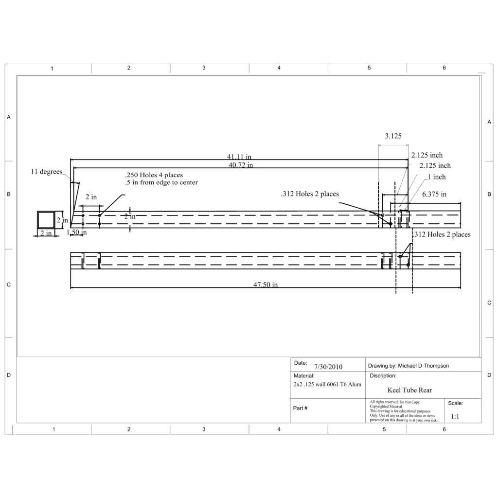
The first thing we will do here is to cut the 72 inch square tube into two pieces. Refer to the first two drawings on this page. The front section is 24.5 inches to the longest point of the 11-degree angle cut. The rear section is 47.5 inches to the longest point of the 11-degree angle cut. I used a chop saw with a carbide blade. You need to be very careful about aluminum chips, (flakes) that fly everywhere when cutting. Be sure to ware safety goggles and clear the area of by standers. I use a shop vac and a hose to the chop saw to get the most of it.
Before drilling the holes in the keel, I need to first drill the holes in the gusset plates.
Fig 1-1
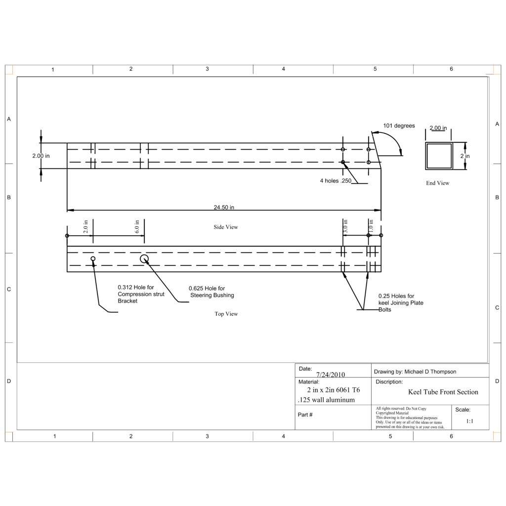
Fig 1-2
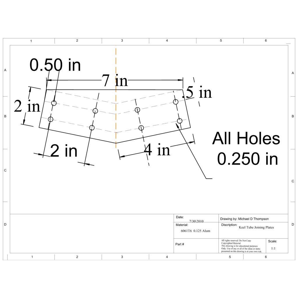
To join these two parts, we have to make a set of gusset plates. These are made from 6061 T6 x .125 thick aluminum plate. Notice that the plates are flat across the top. I need to cut the material to the solid black line on the drawing . Not cut to the dotted line.
The standard is to locate bolt holes at least 1.5 to 2 times the diameter of the bolt from the edge of the material to the center of the hole.
Chapter 1 page 2
Lay out the plates as shown. . Be sure to get the holes in the proper location, and use a center punch to locate the centers of the holes.
I used a drill press for the drilling. A hand drill will work just fine. Just be sure to lay the pieces on a wood block to keep the drill bit from putting a hole in the kitchen table as it passes through the aluminum. Drill the two plates at the same time to assure perfect alignment of the plates to each other. You will need to clamp them together.
I use a small pair of vise grips and wood scraps to protect the plates.
Fig 1-3
Once you have all eight positions drilled, carefully clamp the keel pieces and the gussets together. I used C clamps and wood scraps for backers so as not to gall the aluminum. It takes 4 clamps and three hands to get it all together. It has to be clamped well enough that you can flip the assembly over without it moving.
Fig 1-4
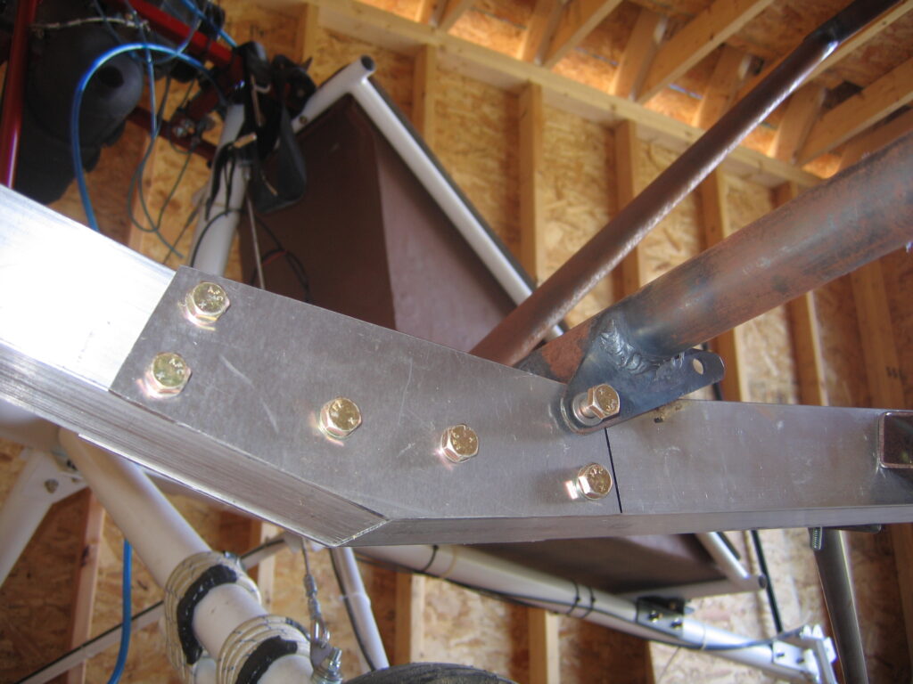
Use a transfer punch to locate the holes for the keel. You do not need to punch all 16 places before you start drilling. Instead, drill one hole at a time, (both sides), and then bolt that one up, is serves as a clamp that can not slip, and allows you to get a perfect fit on the pieces.
{A transfer punch is a punch with an outside diameter that fits the hole who’s center you would like to transfer to another piece of material. }
Use a 1/4 inch drill bill to drill the holes. You can not drill straight through both sides. You must drill one side, then flip the assembly over, and drill the other holes from the other side. Then just run the drill straight through for perfect alignment.
The plates are bolted in place with 8 an() bolts. Mark the gusset plates so you know which one is which. You will want or put them back in the same place and the same side out or they may not fit perfectly.
One thing to mention here is that I actually put this trike together twice. The first time was when fabricating parts, and assembling them for fit. The second time because it needs to be taken completely apart for painting, and adding reinforcement sleeves. This is a good reason to do two things.
1. Mark everything in a manner that identifies its position and orientation, so you can put it back in the same place in the same orientation as when you drilled it.
2. All the bolts in this aircraft have locking nuts for security. You can only safely reuse locking nuts a couple of times. I generally only use them twice. I know guys that won’t use them but once.
In any case, I have jars full of hardware. Grade 5 bolts, plain nuts of all the sizes, and bolts of all the lengths that I need to do the first assembly of my projects. I probably don’t have 30 bucks invested.
Not using lock nuts on the first assembly makes it much easier to disassemble stuff that doesn’t fit the first time around.
One other thing to keep in mind. Don’t put anything together even temporarily, without washers under the nuts and bolt heads. When you tighten nuts against aluminum without washers, it galls the aluminum behind the nut. Also, you can get scribe circles around the nuts from the wrench points. Any of this type of damage weakens the aluminum. So be careful and don’t let this happen. On critical parts this could lead to a failure or having to replace the part.
Chapter 1 page 3
One of the problems with making a one off of anything is that it takes way too much time to make jigs to make exact copies of a part. Even if the project requires more than one of the same item. In other words, you would spend more time making jigs than you would making the part. Of course if you were planning on making many of the same item, then it would pay to make jigs so that each of them could be exactly the same, and thus interchangeable with each other, and from aircraft to aircraft or the same model.
In this case, we are match drilling our parts to make them fit each other, and using the part as a guide to drill the holes in the keel. This makes everything match exactly as long as it remains in the same place it was when you did the match drilling.
{ Match drilling is when you have a part who’s hole needs to be transferred to another part accurately. You clamp the part with the hole’s correct position on top of the part that needs a hole to except a bolt to bolt the two pieces together. Then transfer punch the location and drill straight through the lower material. it is a good idea to do this process in two steps, starting with a drill smaller than the desired hole size. Then re-drill to the correct size while still clamped together. This will tend to eliminate an oblonging of the top hole you are essentially using as a drill bit guide during the process. } Click on match drilling link above for more information.
Before bolting the keel together completely, mark all the parts and disassemble the plates. There are some other holes that need to be drilled, and it is much easier if the keel is in two pieces. Remember, all the parts are match drilled and have to go back to the same place, same orientation as they were when they were drilled.
Chapter 1 page 4
We will be using the match drilling method to drill the holes for the mast mounting plates, and the gear leg mounting plates. We will also drill the pilot hole for the nose gear bushing.
First we have to make the mounting plates for the mast and the gear legs. Use the cad drawings below to fabricate those parts, then continue.
From the rear of the keel tube measure forward 9.5 inches. This will be the back edge of the mast tube mounting plates. Be sure you have the rear half of the keel tube and that you have the correct orientation. The bottom of the keel is the side with the long point of the 11-degree angle cut. See Fig 1-2
Caution: Make sure the plates are on correctly before drilling. In the vertical direction the two .312 in holes are not the same front to back. This means it is possible to get one opposite the other. This would put the corresponding holes in the wrong place side to side, which would weaken the keel tube should you have to re-drill and leave an extra set of holes on one side.
Fig 1-5
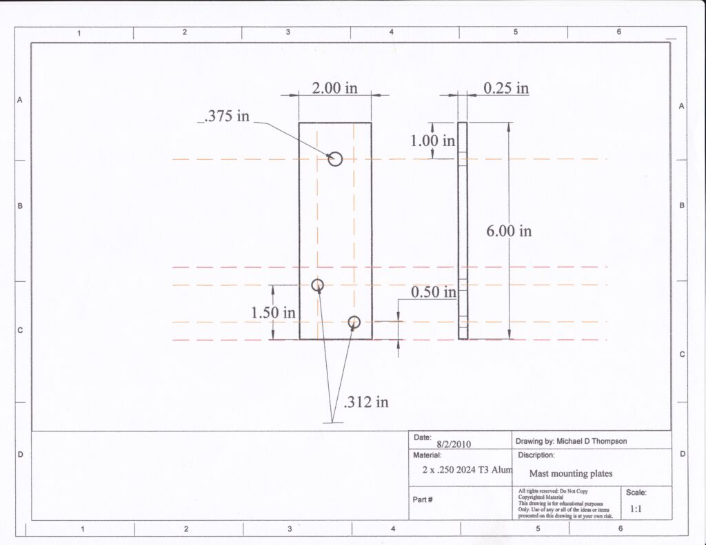
Fig 1-6
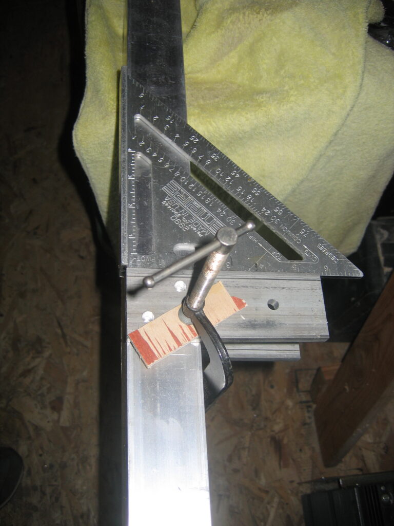
Hold the plates in place making sure they are flush to the bottom of the keel tube, and at 90 degrees to the keel tube. I use a carpenters speed square to do this. It has the ledge on one side of the 90 to let you lock it to the bottom of the keel tube, assuring a perfect fit when the plates are butted to the square. See picture.
I also held a 2-inch square block (not shown) between the plates to help hold everything in place. A piece of keel or mast material about 4 to 6 inches long is ideal. Clamp everything tightly using c clamps and wood backers.
I put the hole that is closer to the top of the keel tube toward the rear and the hole closer to the bottom of the keel tube toward the front. From an strength standpoint, it doesn’t matter which way they go as long as they are the same from side to side.
Once the mast tube plates are in place, and in the correct orientation, use a transfer punch to set the centers of the holes, and match drill them to the keel. Again, drill one side, flip it over and drill the other side. Just make sure both sides are the same before you start drilling. Check twice, drill once. Do not try to drill straight through.
This time after cross drilling for alignment, go ahead and put the bolts in and snug them up lightly.
{Cross drilling for alignment simply means, once you have drilled from each side, especially if you used a hand drill, the hole in the material can be slightly canted. Running the drill bit straight through the assembly will line up the holes you just drilled to make assembly easier. A machinist would tell you to drill everything with a smaller drill and use a reamer to size. But the method above will work just fine as long as the holes were drilled in a drill press or reasonably straight with a hand drill.}
Chapter 1 page 5
Next are the holes in the keel for the gear leg mounting plates.
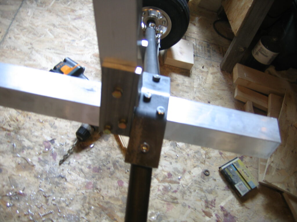
The exact same method is used to drill the holes in the keel for the gear leg mounting plates, as was used on the mast mounting plates.
Fig 1-7
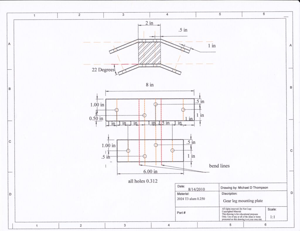
Fig 1-8
See fig 1-2 for the measurements and location of the holes for the gear leg mounting plates. The plates are located 5 7/8 inches from the rear end of the keel to the rear of the gear leg mounting plate.
Important: The plates for the mast and the plates for the gear should not be touching each other. Minor adjustment in the measurement will not affect anything, but rubbing of parts will.
When you fabricated the plates, the holes were located and the bends were done to give the holes the correct orientation top plate to bottom plate. Clamp the plates in place, and use a transfer punch to locate the centers of the holes on the keel tube. Again drilling and bolting one at a time will help keep everything in place. Never try to drill straight through. Drill the top then flip it over and drill the bottom.
Chapter 1 page 6
Next we will drill the hole in the front half of the keel for the pivot bushing for the nose gear.
Fig 1-9
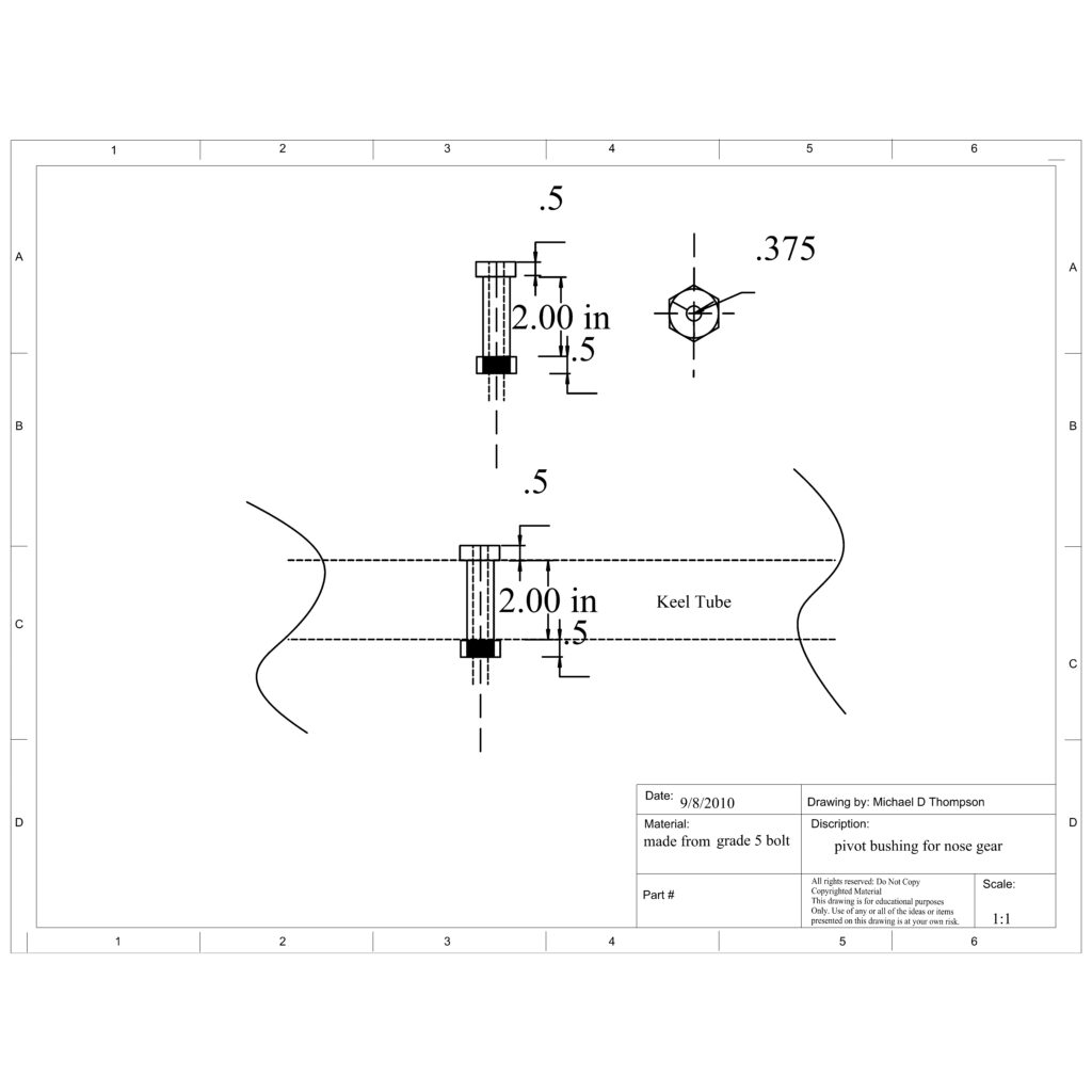
Fig 1-10
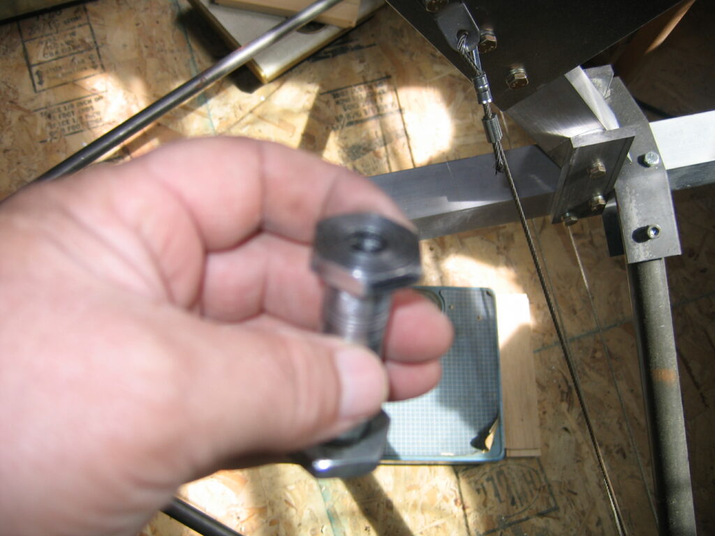
See Fig 1-1 to locate and get the correct orientation for the pivot-bushing hole. Be sure to measure very carefully here. The holes must align perfectly, or the nose gear will lean left or right, or canted forward or aft. Use a Carpenters Square and mark all the way around the tube. Find the center top and bottom and use a center punch to locate the center of the hole before drilling. Use a ¼ inch drill bit to drill a pilot hole, top and bottom. Re measure to be sure the holes are correct.
This hole needs to be opened up to 5/8 inch for the bushing. Without a doubt this is a lot easier using a drill press with a vise on it. But I have done it with a hand drill, and if you take your time and have a good sharp bit, you can get it nearly perfect.
fig 4 This bushing is made from a 5/8 in grade 5 bolt. The bolt has to have a 2 in grip length. Actually just under 2 inches works the best so you can tighten the bushing to the keel without any spacers.
{ The Grip length of a bolt is the part of the shank that is not threaded. When bolting things together, the threads should not end inside the pieces being bolted together. The reason being is, the threaded part of the bolt has less strength in shear than the grip part of the bolt. }
Chapter 1 page 7
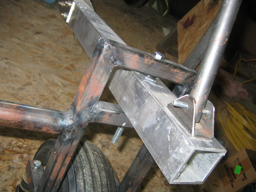
Next drill the hole for the compression strut U bracket. It is the most forward hole in the front half of the keel. See Fig 1-1 to locate and drill this hole.
Fig 1-11
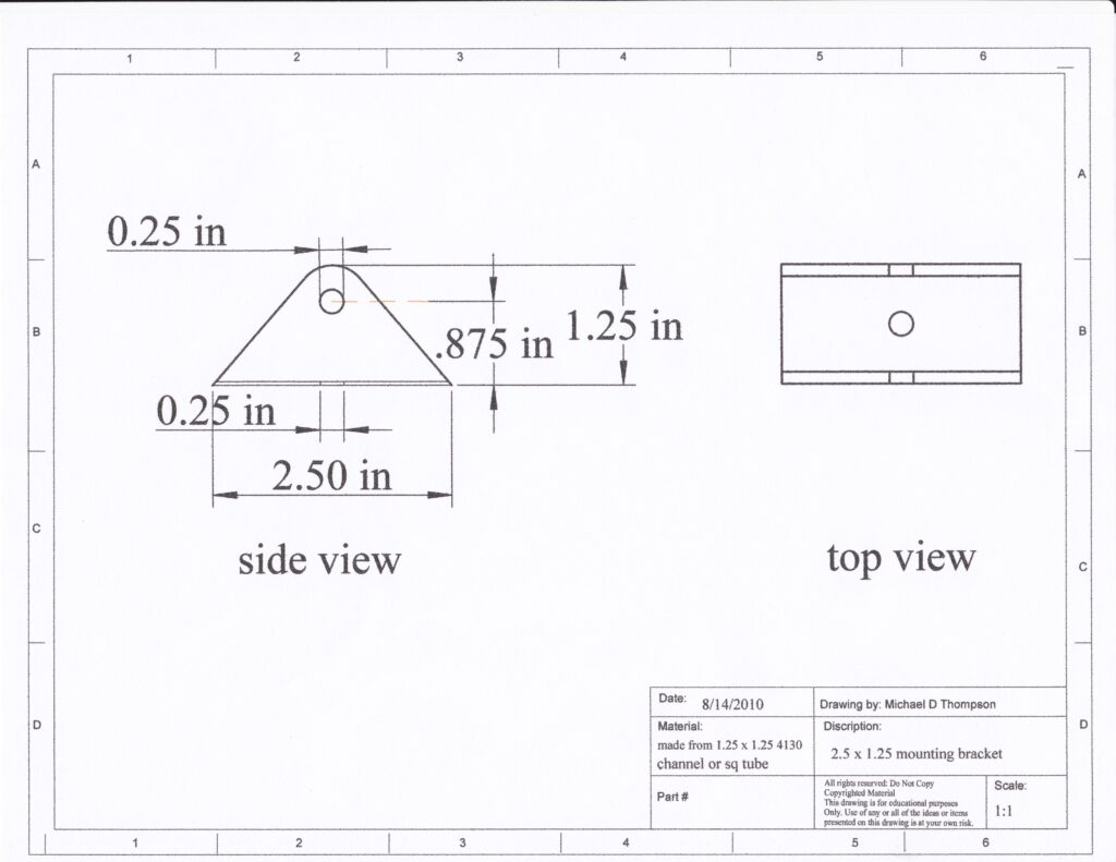
Fig 1-12
Accuracy, is the key to making everything fit nice. On a project like this it is extremely important to take the time to do it right. If you are using any of this information to do a project of your own, remember a few things.
One, this is how I did it. That doesn’t mean you will or can get the same result. You are the manufacturer and the quality control guy. You are the test pilot who’s ass is on the line here. Take your time and do it right.
Two, nobody was born a pilot. We all need to take lessons tolearn to fly and just like every other skill, it takes practice and more practice to be safe. Has anybody ever successfully taught themselves to fly safely, no! They may be getting around the patch without killing themselves, but that will probably change.
Three and most important ! “Get lessons” no matter what it takes to get there. I had 5000 hrs in airplanes, mostly teaching others, and still had to take lessons to learn to fly weight-shift aircraft. Just because you don’t need a license to fly Ultralight aircraft, doesn’t mean it knows how to fly itself while you sit there not knowing what to do.